Rubber Mold and its Types
- Post On15.04.2021
- ByNiket Lachake
Molding
A mold can be described simply as at least two pieces of material (typically steel) that, when fitted together, form a cavity that replicates the shape of the product. This is a straightforward kind of mold. Molding (vulcanization) is an essential curing process in which uncross-linked rubber is placed in a heated mold, which gives it the final product shape and then vulcanizes the material.
Mold
It can be as small as a minute or as large as an auto part, and it can have a single cavity to make one product at a time or enough cavities to make a hundred or more. Although urethanes and silicones can be introduced as solids or liquids, most rubber molding is based on introducing a solid compound into a mold. In this chapter, only solids will be discussed. To close the mold and thus form the product shape, relatively high mechanical pressure is required; a press provides this pressure. As a result, the mold must be strong enough to avoid crushing. Tool steel hardened to a Rockwell C hardness of around 60 may be required.
Designing of the Mold
This depicts a cross-section through the centre of a basic compression mould design. It is critical that the two halves of the mold match up (fit accurately together). Pins built into the top section fit snugly into holes drilled into the bottom half in this case. Any looseness between the pin and the hole may cause the top and bottom halves of the product to be out of alignment. If the fit is too tight, manually opening the mold may be difficult. Because the number of compound materials expands with heat by at least an order of magnitude more than steel, they will shrink correspondingly when removed from the steel mold. To compensate for the difference in expansion between rubber and steel, mold dimensions are typically designed to be around 1.5 to 1.8 percent (based on linear dimensions) greater than those required in the rubber product. This percentage of vulcanizate shrinkage may be greater for FKM and silicone compounds and less for filler-heavy compounds. Around the mold cavity, overflow (flash or spew) grooves are machined. In theory, this is correct.
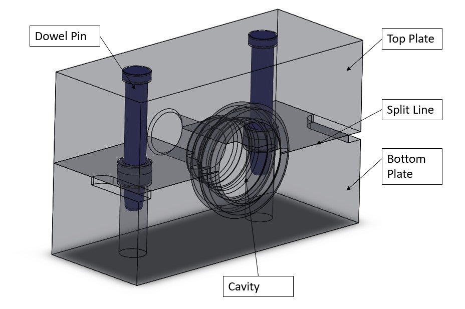
Fig. Single cavity mold

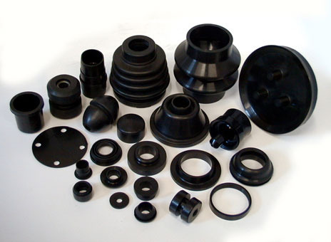
Fig. Rubber molded parts
To have more rubber than the cavity volume During mold closure, it is not uncommon to see material filling the cavity, then spilling out of the overflow grooves, and even across an area outside the grooves known as the land, and then out of the mold. This excess material is referred to as flash. Adding compound to the mold There are several methods for introducing the compound into the mold, some of which require modifications to the basic design. They each provide advantages that the others do not.
- The most basic design (compression molding) involves placing pieces of rubber compound in the top and bottom cavity and compressing them with the top half of the mold.
- The first modification is transfer molding, which can be visualized as drilling holes through the outside of a compression mold's top mold half into the cavity.
- As a result, the mold can remain closed while rubber compound is introduced into the cavity through these holes using the force exerted by the press platen.
- Injection molding occurs when a separate device, unrelated to the press platen, injects the compound through the holes.
Compression Molding
This is the simplest, cheapest, and most common of the three basic molding techniques. It is best suited to small-scale production, say, from fifty to a few thousand of each product per year. The various stages of the molding process are depicted in figure. One of the keys to successful molding is adequate air removal while the mold cavity fills with rubber.
Uncured pieces of compound placed in the mold are referred to as preforms, billets, or load weights. An elliptically shaped extrusion cut to length from a Barwell could be used. This shape is important and was purposefully chosen so that air in the mold cavity has a free path of escape when the mold begins to close, as shown in Figure
The weight of this preform is typically chosen to be a few percent (two to ten percent) greater than the weight of the final product to ensure a fully formed product and to provide an extra 'push' for the expulsion of any residual trapped air. The bottom cavity is filled with the preform, and the top mold section is placed on top of it by hand. If many moldings are to be produced, it is often advantageous to attach the two halves of the mold to their respective press platens, as shown in figure below, to reduce manual handling and labour costs.
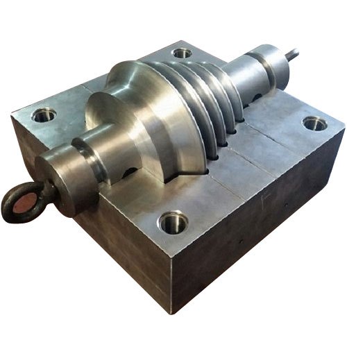
Fig. Single cavity compression mold
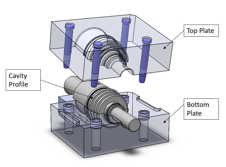
Fig. Designed mold for the compression molding
Because flash frequently spills over the land during compression, a large land area between the flash groove and the outside of the mold may 'fine tune' backpressure control. A large land distance restricts flow when the mold is nearly closed, potentially increasing backpressure, which would be beneficial with low viscosity compounds. For high viscosity materials, the opposite may be true, i.e., a small land area with deep flash grooves is preferable. For the same force exerted by the press ram, this would also promote greater pressure at the moment before full mold closure. Radial grooves connecting the flash grooves to the outside of the mold should also aid in the exit of high viscosity compounds. The press must apply a certain amount of pressure in order for the compound to flow into the cavities and the mold to properly close. The goal is to achieve a thin flash, ideally around 0.05 mm. The pressure exerted on the product in the mold at closure is given by the area of the press rams divided by the projected area of rubber and flash between the mold halves multiplied by the line pressure at the press.
The required pressure is typically 8-12 MPa and varies depending on factors such as compound viscosity and mold cavity complexity. The mold is built to withstand the high stress involved. It is worth noting that the area of projected rubber may be smaller at the start of mold closure because the rubber has not yet fully spread throughout the mold cavity. Depending on the exact set-up, more of the ram's force may briefly act on delicate inserts or parts of the mold. If this is not taken into account, it has the potential to cause damage. Material flow in a mold is a complicated process, especially in compression molding. The rubber in the cavity is subjected to large temperature changes, translating to viscosity variations, causing the compound's flow characteristics to change continuously. Mold designers now have access to finite element analysis packages, which describe the material flow patterns in the mold. In most of the rubber industry, the use of such design aids is in its early stages.
Transfer Molding
We can effectively convert a compression mold into a transfer mold by drilling transfer holes through it and placing a metal collar (transfer pot) on the closed mold to surround the holes. All that remains is to fill the pot with rubber compound and force it through the holes by inserting a piston (plunger) into the pot and using the press platens to force the piston to push the compound down through the pot into the closed mold cavity. In the rubber industry, this conversion is used. Alternatively, the transfer pot can be designed as an integral part of the mold, with the piston attached to the upper press platen. Because rubber is a thixotropic non-Newtonian fluid, shear between it and the walls of the transfer holes reduces its viscosity, making it easier for the compound to enter the mold cavity. Shear also heats the compound, reducing viscosity and hastening cure.
Design Consideration for the Transfer Mold
The piston can be slightly tapered to facilitate product removal after cure. Keep in mind that the mold now has three sections: the piston or plunger, the top half of the mold, and the bottom half. The middle section may float upwards as the piston descends before the transfer is complete. If the surface area of the pot is less than the total projected area of rubber between the top and bottom mold halves, the reaction force pushing the top mold section up will be greater than the force of the piston pushing the top mold section down through the rubber in the pot. The top half of the mold will float up, allowing the compound to leak out between the now open parting line until the piston bottoms out, closing the mold. As a result, there is much flash between the mold halves. If the pot's surface area is sufficiently large, as it should be, the mold closes with minimal flash. Transfer molding can use pressures of up to 14 MPa, which is slightly higher than compression molding.
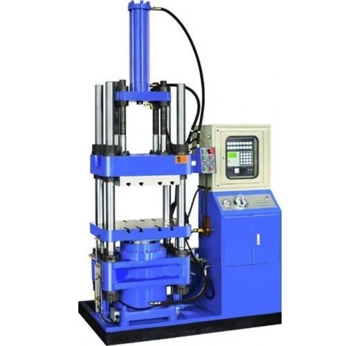
Fig. Transfer molding machine
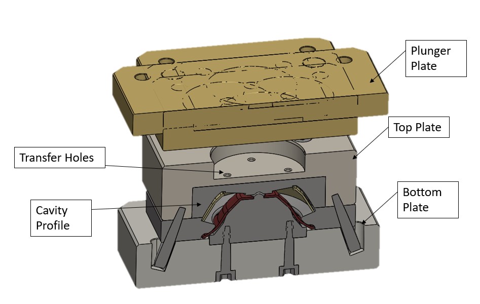
Fig. Transfer mold
Advantages
- The mold remains closed during cure, there is a much better chance of reduced flash thickness and, as a result, a better closure dimension tolerance (the product dimension that includes the variable flash thickness, which is theoretically assumed to be zero).
- Frictional heating during transfer causes the compound to enter the cavities at a higher temperature, reducing overall cure time, especially for large parts.
- Some compounds sit on the shelf' before use, there is a risk of ingredients blooming to the surface, which could interfere when the compound is bonded to metal. It is suggested that in transfer molding, as the compound moves through the transfer holes, this bloom tends to ‘re-dissolve, thus improving the prospect of a consistent bond.
- There is no need for complicated preform preparation or precise positioning in the mold cavity.
- The technique is generally better for rubber to metal bonding.
Disadvantages
- The plunger and transfer pot are not included.
- The cured rubber pad left in the transfer pot should be thick enough to be removed in one piece. In a compression mold, the pad represents waste material, and the amount can be greater than the flash waste.
- There is a risk that the compound will sweep across cemented inserts, removing some cement. If this is the case, the adhesive manufacturer should be contacted.
- A blemish will be left when the cured rubber attached to the product in the transfer holes is cut off. This could be a problem, for example, if all of the product's surfaces act as a seal.
Injection Molding
An injection mold comprises a cylinder (injection barrel) with a ram or screw inside it that allows the rubber compound to be moved towards a nozzle at its end. The nozzle is then pressed against a hole drilled in the upper half of a closed mold. This hole is then linked to smaller holes (gates and runners) that enter the mold's cavities. The compound can be fed into the barrel as a continuous strip or as granules via a hopper, as in plastic injection molding. A ram fits more tightly in the barrel than a screw, resulting in less leakage backwards through the barrel; it is also less expensive than a screw as it moves towards the nozzle, the screw 'mixes' the compound, producing more frictional heat and thus higher temperatures, resulting in more effortless flow and shorter cure times. The use of a ram and a screw is standard.
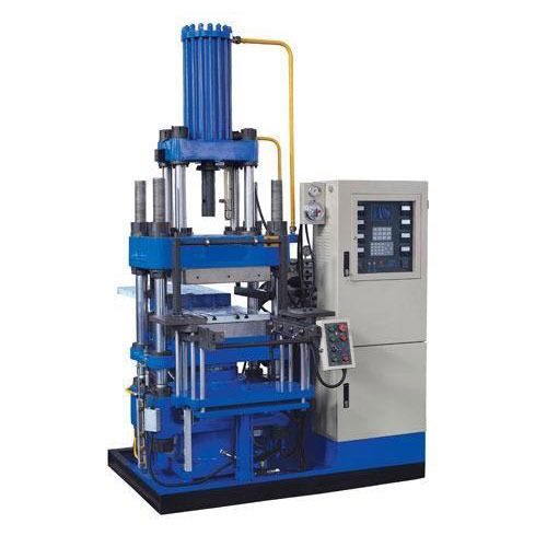
Fig. Injection molding machine
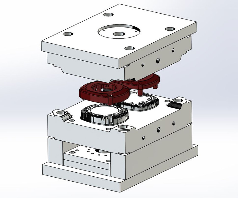
Fig. Injection mold
Advantages
- Cure temperatures can be significantly higher than those used in compression or transfer molding.For example, injection temperatures of 160 °C and mold temperatures of 180-190 °C. High temperatures result in shorter cure times; for thin cross-sections, one or two minutes is possible.
- Because the temperature of the compound entering the cavity is closer to the molding temperature, there is much less thermal volume expansion of the rubber during cure, resulting in much less internal pressure build-up and a much lower tendency to backrind.
- No complicated preform is required.
- Flash is significantly reduced or eliminated.
- Air entrapment is significantly reduced.
- The system is capable of high levels of automation, similar to plastic injection molding.
- It is well-suited to high-volume production.
Disadvantages
- The molds must be able to withstand extremely high injection pressures. This necessitates the use of high hardness steel molds and more precise tooling.
- When gates and runners are added to the mold, the cost significantly exceeds compression or transfer molding.
Post your comment